Nickel Metal Hydride Battery Safety Notes
Nickel Metal Hydride
3.0 Nickel Metal Hydride (NiMH)
3.1 NiMH Principles of Operation
The principles in which NiMH cells operate are based on their ability to absorb, release, and transport (move) hydrogen between the electrodes within the cell. The following sections will discuss the chemical reactions occurring within the cell when charged and discharged and the adverse effects of overcharge and overdischarge conditions.
The success of the NiMH battery technology comes from the rare earth, hydrogen-absorbing alloys (commonly known as Misch metals) used in the negative electrode. These metal alloys contribute to the high energy density of the NiMH negative electrode that results in an increase in the volume available for the positive electrode. This is the primary reason for the higher capacity and longer service life of NiMH batteries over competing secondary batteries.
3.2 Charging Chemical Reaction
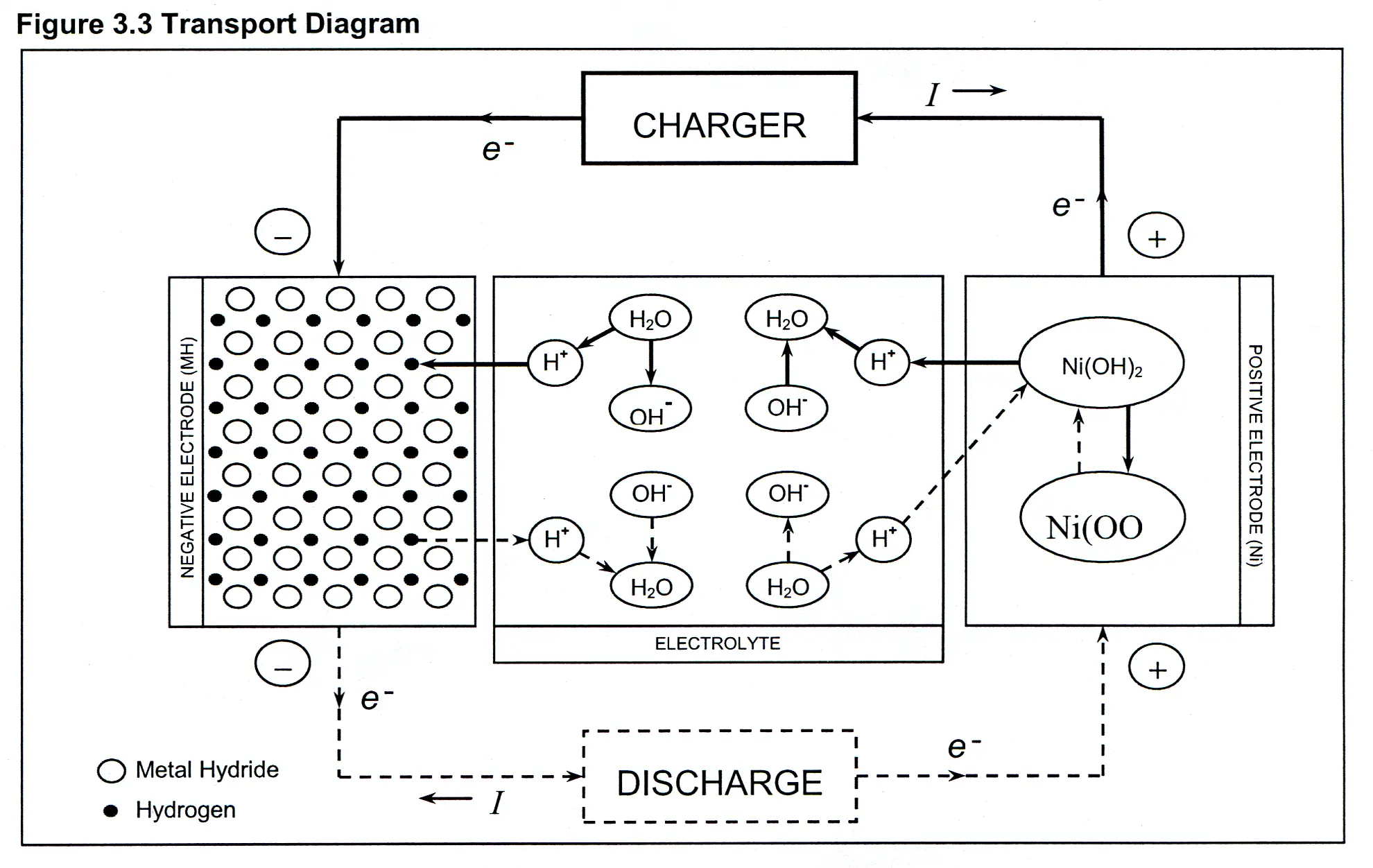
When a NiMH cell is charged, the positive electrode releases hydrogen into the electrolyte. The hydrogen in turn is absorbed and stored in the negative electrode. The reaction begins when the nickel hydroxide (Ni(OH)2) in the positive electrode and hydroxide (OH¯) from the electrolyte combine. This produces nickel oxyhydroxide (NiOOH) within the positive electrode, water (H20) in the electrolyte, and one free electron (e¯). At the negative electrode the metal alloy (M) in the negative electrode, water (H20) from the electrolyte, and an electron (e¯) react to produce metal hydride (MH) in the negative electrode and hydroxide (OH¯) in the electrolyte. See Figure 3.2 Chemical Equations and Figure 3.3 Transport Diagram.
Because heat is generated as a part of the overall chemical reaction during the charge of a NiMH cell, the charging reaction described above is exothermic. As a cell is charged, the generation of heat may not accumulate if it is effectively dissipated. Extreme elevated temperatures may be experienced if a cell is excessively overcharged. See Section 3.4 Overcharge and 3.5 Overdischarge.
Figure 3.2 Chemical Equations| Positive Electrode: | Ni(OH)2 + OH - | charge ⇄ discharge | NiOOH + H2O + e - |
| Negative Electrode: | M + H2O + e- | charge ⇄ discharge | MH + OH - |
| Overall Reaction: | Ni(OH)2 + M | charge ⇄ discharge | NiOOH + MH |
3.3 Discharge Chemical Reaction
When a NiMH cell is discharged, the chemical reactions are the reverse of what occurs when charged. Hydrogen stored in the metal alloy of the negative electrode is released into the electrolyte to form water. This water then releases a hydrogen ion that is absorbed into the positive electrode to form nickel hydroxide. See Figure 3.2 Chemical Equations and Figure 3.3 Transport Diagram. For NiMH cells, the process of moving or transporting hydrogen from the negative electrode to the positive electrode absorbs heat and is therefore endothermic. Heat continues to be absorbed until the cell reaches a state of over discharge, where a secondary reaction occurs within the cell resulting in a rise in temperature. See Section 3.5 Over discharge.
3.4 Overcharge
Nickel Metal Hydride cells are designed with an oxygen-recombination mechanism that slows the buildup of pressure caused by overcharging. The overcharging of a cell occurs after the positive electrode 1) no longer has any nickel hydroxide to react with the hydroxide from the electrolyte, and 2) begins to evolve oxygen. The oxygen diffuses through the separator where the negative electrode recombines the oxygen with stored hydrogen to form excess water in the electrolyte. If this oxygen-recombination occurs at a slower rate than the rate at which oxygen is evolved from the positive electrode, the result is in a buildup of excess oxygen (gas) resulting in an increase in pressure inside the cell. To protect against the first stages of overcharge, NiMH cells are constructed with the negative electrode having a capacity (or active material) greater than the positive electrode. This helps to slow the buildup of pressure by having more active material available in the negative electrode to effectively recombine the evolved oxygen. See Figure 3.4, Useable Capacity Diagram.
Excessive overcharging of a NiMH cell can result in permanent loss in capacity and cycle life. If a cell is overcharged to the point at which pressure begins to build up, elevated temperatures are experienced and can cause the separator to lose electrolyte. The loss of electrolyte within the separator (or “separator dry out”) inhibits the proper transport of hydrogen to and from the electrodes. Furthermore, if a cell is severely overcharged and excessive amounts of oxygen (gas) are evolved, the pressure may be released through the safety vent in the positive terminal. This removes elements from within the cell needed for proper function. To protect against the damaging effects of overcharging, proper charge terminations must be used. See Section 3.8.2 NiMH Charge Termination.
Figure 3.4 Useable Capacity Diagram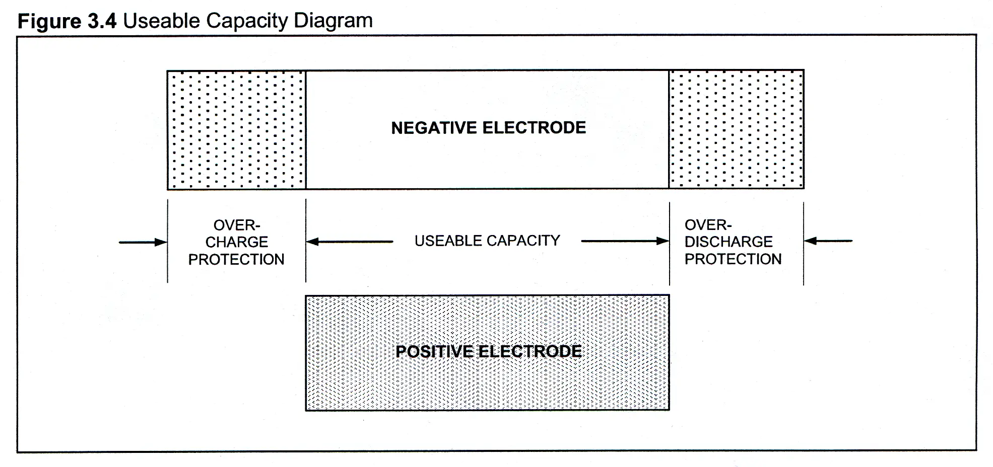
3.5 Over Discharge
There are two phases to the over discharging of a NiMH cell. The first phase involves the active material of the positive electrode becoming fully depleted and the generation of hydrogen gas begins. Since the negative electrode has more active material (metal hydride), it has the ability to absorb some of the hydrogen gas evolved by the positive electrode. Any hydrogen not absorbed by the negative electrode begins to build up in the cell generating pressure. The second phase begins when the entire negative electrode is fully depleted of active material. Once both electrodes are fully depleted, the negative electrode absorbs oxygen contributing to the loss of useable capacity.
Extreme over discharge of a NiMH cell results in excessive gassing of the electrodes resulting in permanent damage in two forms. First, the negative electrode is reduced in storage capacity when oxygen permanently occupies a hydrogen storage site, and second, excess hydrogen is released through the safety vent reducing the amount of hydrogen inside the cell. To protect against the damaging effects of over discharging, proper end of discharge terminations must be used. See Figure 3.7.4 NiMH Low Voltage Disconnect or Voltage Cutoff.
3.6 Rate Capability
The maximum rate a cell is able to achieve for a short burst is dependent on the cell construction, temperature and manner in which it is assembled into a pack. This will be clearer after looking at Section 3.7.1 NiMH Capacity.
3.7 NiMH Discharge Characteristics
The discharge characteristics of NiMH batteries (both cells and battery packs) depend on many factors. These factors include capacity, voltage, discharge rate, discharge termination (or voltage cutoff), matching (of cells within a battery pack), internal resistance, and temperature.
3.7.1 NiMH Capacity
Engineers and designers are usually most interested in how long a battery will supply the current needed to run a piece of equipment or a device. The length of time is directly proportional to the capacity of the battery and discharge rate. Defined as C, capacity is the electric current content of a battery expressed in ampere-hours (Ah) or milli-ampere-hours (mAh). The capacity of a battery is determined by discharging the battery at a known constant current until a predetermined end voltage is reached. The amount of time it takes to discharge a battery to the end voltage multiplied by the rate of current at which the battery was discharged is the rated capacity of the battery. Therefore, a battery would be rated at 1500 mAh if it was discharged at a rate of 150 mA to an end voltage of 1.0 volt per cell and it discharged for 10 hours.
For clarification, the rate of current (charge or discharge) that is applied to a battery is often defined in terms of the rated capacity C of a battery. For example, a battery rated at 1500 mAh that is discharged at a rate of C/2 (or 0.5C) will have 750 mAh discharged from the battery per hour. Thus, a discharge rate of C/2 of a 1500 mAh battery is 750 mA, but this does not mean the battery will last for 2 hours!
One of the biggest misconceptions regarding NiMH cells is that rated capacity is the capacity that will be received by the user. This would only be true if the user charged and discharged at the same rates of current at which the cell was graded.
Rated capacity has been defined by the International Electrotechnical Commission (IEC) in document #61436.1.3.4, as a charge at a rate of 0.1C for a period of 16 hours. This is followed by a discharge of 0.2C to a voltage of 1.00V per cell. However this number sometimes can be convoluted by Maximum, Typical, and Minimum cell ratings. For example, a lot of 1000 cells might range from 1000 mAh to 850 mAh. The maximum capacity would then be 1000 even though only a small number of the cells attain this capacity. The nominal capacity would be 900 mAh, and the majority of the cells tested would attain this capacity. All those cells must conform to the minimum of 850 mAh. We have found that to be considered with other manufacturers, we must also conform to this cell rating procedure
Results derived when testing NiMH technology battery packs for capacity can change dramatically with variation in:
- Temperature
- Charge Rate
- Discharge rate
- Number of Cells in the Pack / Increase in Voltage Cutoff per Cell
All of these conditions must be taken into to account when a comparison is being made from pack to pack, and cell-to-cell.
Polarizations
When a NiMH technology cell is subjected to a flow of current a chemical change occurs within the cell. The obstacles to current flow are known as polarizations. The polarizations are:
- Ohmic
- Ohmic polarization is the internal impedance of the cell against current flow. The impedance has a corresponding voltage drop, which can be seen in the voltage profile of any NiMH cell. During charge current this voltage is added to the overall voltage of the cell. However during discharge this voltage is subtracted from the overall voltage of the cell. The magnitude of the voltage drop will be directly proportional to overall impedance internal to the cell and the rate of current (charge/discharge) the cell is subjected to. If a cell has higher impedance, the drop will be greater. As the current applied to the cell is increased the voltage drop will increase. This is critical when a predetermined termination voltage is set. If a cell is discharged at a high enough current it can instantly force the cell voltage below 1.00V, even though there is almost 100% capacity remaining.
- Concentration
- Concentration polarization is directly proportional to the surface area of the anode and cathode of the cell. The greater the surface area of these active plates, the greater the reduction in this polarization. This is determined during the engineering and manufacturing of the cell itself, and little can be done after that.
- Activation
- Activation polarization is the amount of energy expended to cause the chemical reaction. Nothing is 100% efficient, so any chemical change expends energy. At a molecular level temperature has a great effect on the amount of energy it takes to make a reaction transpire. Generally all rating is performed at 20-25°C, as the temperature increases, or decreases the amount of energy on discharge will change.
Knowing what affects the NiMH chemistry, we can fashion testing to isolate any variable that may cause inconsistent results.
For example, a cell is charged at a 0.5 C with a –dV termination. When capacity testing is performed at a 0.5C discharge expect to see between 5-7% reduction in cell capacity over the IEC rating. This is explained first by the Ohmic polarization on discharge, and secondly due to the variation in charged energy using a –dV charge regime.
In order for a –dV to be seen on a NiMH cell it must be subjected to a small margin of overcharge. This overcharge condition forces the voltage depression. It occurs when all of the active material in the cell is chemically reacted, and oxygen evolves and then diffuses into the negative electrode. The negative electrode is designed to be larger than the positive so it accepts a portion of this oxygen diffusion, however pressure is still generated within the cell, which generates heat. The heat then causes the cell voltage to drop. A direct comparison of the energy input during charge and output during discharge cannot be made because a portion of the input energy was wasted on oxygen evolution and was never recombined. In order to derive a % of rated capacity, we must calculate the energy received during discharge of our test, with that cells IEC rated capacity
3.7.2 NiMH Voltage
The discharge voltage profile of a NiMH battery is considered “flat” (see Figure 3.7.2 C/10 Discharge Profile @ 25°C) and varies with the rate of discharge and temperature. As a fully charged battery is discharged the voltage begins at about 1.5 volts followed by a sharp drop to around 1.3 volts. The voltage remains between 1.3 to 1.2 volts for about 75% of the profile until a second sudden drop in voltage occurs as the useful capacity of the battery begins to deplete. At this point is where the discharge current (or load) is terminated at a safe voltage level (see Section 5.4 Low Voltage Disconnect or Voltage Cutoff). With elevated discharge rates, the entire discharge profile is lowered by losses in ohmic polarizations (internal resistance). At high temperatures, the discharge profile is raised by an increase in potential (voltage) between the electrodes. At temperatures below 10°C (50°F), concentration polarization significantly lowers the voltage and the useable capacity. This is caused by an increase in energy required to transport molecules within the battery. See Section 2 Principles of Operation and Construction.
The industry standard for the rated voltage of a NiMH cell is 1.2 volts. This value is the nominal voltage of a cell that is discharged at a rate of C/10 at a temperature of 25°C (77°F) to an end voltage of 1.0 volt. This industry standard is used primarily to call out the rated voltage of battery packs. For example, a battery pack made of three cells in series would be rated as a 3.6-volt battery pack. Figure 3.7.2, C/10 Discharge Profile @ 25°C, shows that the nominal voltage of a NiMH cell is just above 1.2 volts.
For technical applications and calculations, the nominal voltage of a battery pack provides a useful approximation of the average voltage throughout discharge. The nominal voltage can be simply calculated after the battery has been discharged. To calculate the nominal voltage, divide the batteries energy [watt-hours (Wh)], by the capacity, [ampere-hours (Ah)]. This calculation proves beneficial when a battery is discharged at high temperatures, since nominal voltage will increase under these conditions.
Figure 3.7.2 C/10 Discharge Profile @ 25°C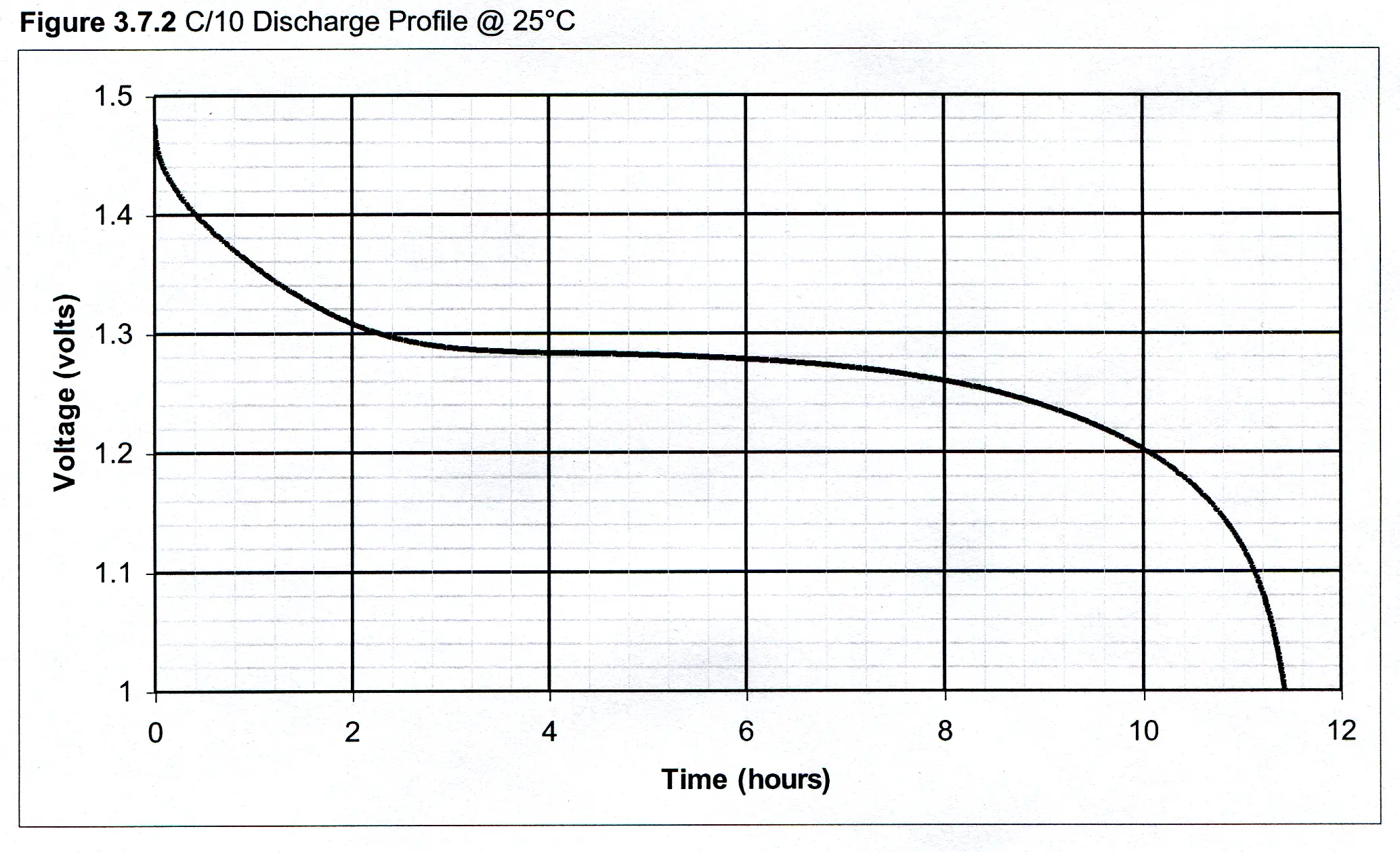
3.7.3 NiMH Discharge Rate
The delivered capacity and nominal voltage of a battery are dependent on the rate of current at which a battery is discharged. For NiMH batteries, there is no significant affect on capacity and voltage for discharge rates below 1C. A reduction in the nominal voltage occurs for discharge rates between 1C and 3C for all the NiMH cell sizes with the exception of the high rate series of cells.
3.7.4 NiMH Low Voltage Disconnect or Voltage Cutoff
To prevent potential irreparable harm to a battery due to polarity reversal of one or more cells during discharge, the load (discharge current) must be terminated prior to the battery being completely discharged. Damage can be avoided by terminating the discharge at a point where essentially all capacity has been obtained from the battery, but a safe voltage level remains. Removing the load in this manner is referred to as Low Voltage Disconnect or Voltage Cutoff. Capacity of a battery is slightly dependent on the Voltage Cutoff used at the end of discharge. Continuing the discharge to lower endvoltages can slightly increase the delivered capacity, yet if the end voltage is set below the recommended Voltage Cutoff the cycle life of the battery will be decreased. The following table gives the Voltage Cutoff recommendations for discharge rates of less than 1C:
Figure 3.7.4 Voltage Cutoff Schedule| Number of Cells in Series | Low Voltage Disconnect/Voltage Cutoff |
|---|---|
| 1 to 6 | 1 volt per cell |
| 7 to 12 | [(MPV-150mV)(n-1)]-200mv |
Where MPV is the single cell midpoint voltage at the given discharge rate (typically 1.3) and n is the number of cells in the pack. For discharge rates greater than 1C the MPV will decrease.
3.7.5 NiMH Matching
Matching refers to the grouping of individual NiMH cells with similar capacities to be used within a battery pack. Typically, the matching of the cells in a battery pack is within 2%. Matching eliminates the potential of reversing the polarity of one or more cells in a battery pack due to the capacity range of the combined cells being too great. Matching becomes more critical as the number of cells in the battery pack increases. This is due to the potential of one cell having a capacity significantly lower than the average capacity of the other remaining cells. As a result, the lowest capacity cell has the potential to reverse polarity while the other cells remain at safe voltage levels before reaching the voltage cutoff. If a battery pack has one or more cells reversed before the Voltage Cutoff is reached, the performance and cycle life will be reduced.
3.7.6 NiMH Internal Resistance
The internal resistance of NiMH cells varies depending on cell size, construction, and chemistry. Different materials are used in various NiMH cells to achieve desired performance characteristics. The selection of these materials also affects the internal resistance of the cell. Since NiMH cells of various sizes, construction, and chemistry are different, there is no one value of internal resistance that can be defined as a standard. The internal resistance for each cell is measured in m at 1000Hz.
3.7.7 NiMH Temperature
To obtain the optimum capacity and cycle life of a NiMH battery, the recommended range of temperature when discharging a standard battery is 0°C (32°F) to 40°C (104°F). Due to the endothermic discharge characteristics of NiMH cells, the discharge performance is increased moderately at higher temperatures, yet the cycle life will be lowered. At lower temperatures, performance decreases more significantly due to the cells polarization. See Section 3.7.7. This is caused by a decrease in transport capabilities (the ability to move ions within the electrodes). For most NiMH batteries, the following chart shows the typical affect of temperature on capacity at a C/5 discharge rate.
Figure 3.7.7 Discharge Capacity vs. Temperature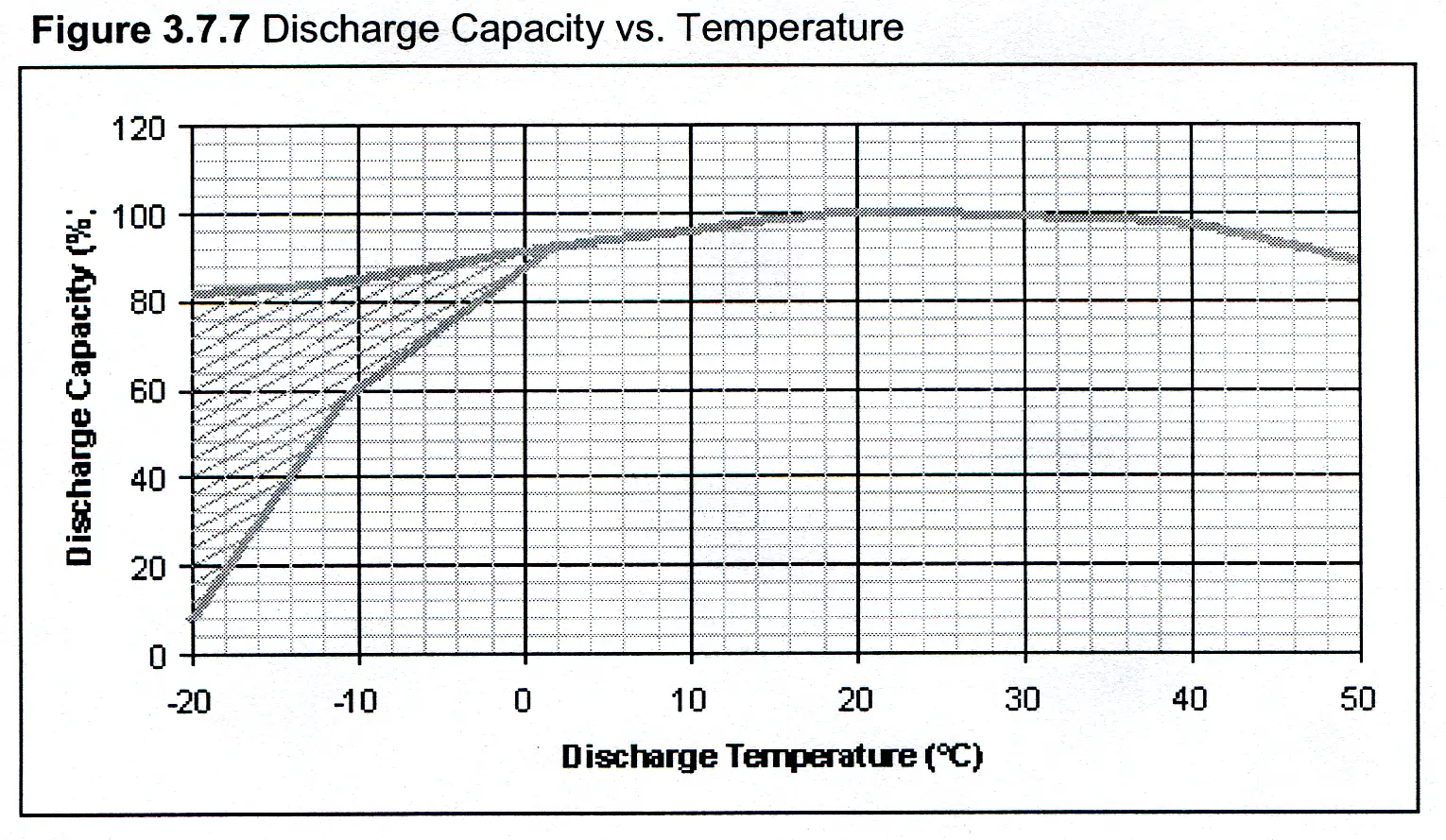
3.8 NiMH Charge Characteristics Overview
The charging, or recharging, of NiMH batteries (both cells and battery packs) is the process of replacing the energy that has been removed or discharged from the battery. The performance of the battery, as well as the cycle life, depends on effective charging. The three main criteria for effective charging are:
- Choose the appropriate charge rate
- Select the appropriate charge termination technique
- Control the temperature
3.8.1 NIMH Charge Rates
As the capacity of NiMH cells has increased, so has the demand for faster charging. This leads to higher charge rates, which requires care to ensure a complete charge while minimizing the potential damage of overcharging. Slow charging is still a reliable method, but not all batteries can be slow charged without some type of termination. Some NiMH cell chemistries have higher capacities and are better suited to the more popular fast charging methods.
3.8.2 NIMH Charge Termination
Properly controlling the charging of a NiMH battery is critical to achieving optimum performance. Charge control incorporates proper charge termination to prevent overcharging the battery. The overcharging of a battery refers to the state at which the battery can no longer accept (store) the energy entering the battery. As a result pressure and temperature builds up within the cell. If a cell is allowed to remain in the overcharge state, especially at high charge rates, the pressure generated within the cell can be released through the safety vent located within the positive terminal. This may cause damage to the battery reducing cycle life and capacity.
To prevent damage occurring to the battery, charge termination is one of the most critical elements to be applied to any method of charge control. Charge control may utilize one or more of the following charge termination techniques. The three primary techniques of charge termination are time, voltage, and temperature.
3.8.2.1 Time
Time-based charge control techniques terminate charging of the battery after a predetermined length of time. This technique should be used when slow charging to avoid excessive overcharge, and used as a backup secondary termination for all fast charge methods.
3.8.2.2 Voltage
Charge control techniques that are voltage-based are attractive because of the predictable charge voltage profile of a NiMH battery (see Section 3.8.3 Charge Termination Nomenclature). The charge voltage profile of a NiMH battery is consistent regardless of the batteries state of charge. However, the voltage-based charge termination techniques generally occur after a battery has already reached the overcharge state. In addition, the voltage-based techniques may not be applicable at rates below C/4 and are prone to false termination due to RF noise. It is also necessary to include temperature-sensing devices to terminate the charge if the temperature becomes too high. Such devices include thermostats and PTC resettable fuses.
Peak Voltage Detect (PVD)
The recommended technique for voltage-based charge termination is peak voltage detect or PVD. This technique involves sensing the drop in voltage after the battery has reached its peak voltage and becomes overcharged (see Section 3.8.3 Charge Termination Nomenclature). This technique is recommended because it reduces the risks of overcharging from that of other voltage charge termination techniques. To prevent substantial damage to a battery, a maximum drop in voltage of 3 mV per cell before termination is recommended to limit the amount of overcharge on the battery. Additionally, the sampling rate of the charger IC is more frequent to increase sensitivity.
Negative Delta V (-ΔV)
Negative delta V (-ΔV), like PVD, follows the same concept of sensing the drop in battery voltage after the battery has reached its peak voltage. The difference is the change or drop in voltage is increased to 3 to 5 mV per cell before the charge is terminated. This technique allows the battery to be exposed to longer periods of overcharge and is not normally recommended. See Section 3.8.3 Charge Termination Nomenclature
3.8.2.3 Temperature
The exothermic nature of NiMH batteries under charge refers to the generation of heat as the battery is charged especially just before and during overcharge. The temperature-based charge termination senses this temperature rise and terminates the charge when the battery has reached a temperature that indicates when full charge is being approached. This type of charge termination is recommended because of its reliability in sensing overcharge, yet it requires care in the selection of set points in the charge circuitry to avoid premature charge termination or failure to detect the overcharge when the battery is exposed to extreme temperature environments.
Change in Temperature (ΔT)
Change in temperature or ΔT is the technique that measures the difference of the rise in battery temperature above the starting (ambient) temperature during charge. The charge is terminated when the rate of change in temperature reaches a predetermined value. See Section 3.8.3 Charge Termination Nomenclature
Change in Temperature/Change in time (dT/dt)
The recommended technique for temperature-based charge termination for all fast-charging methods is dT/dt (see Section 6.3 Charge Termination Nomenclature). This technique monitors the change in temperature T verses the change in time t, and is considered most accurate because it senses the start of overcharge earlier than other techniques. Baseline dT/dt temperature termination is 1°C per minute, but varies according to pack design. When using a dT/dt termination, a top-off charge is suggested in order to fully charge the battery (see Section 3.8.6.5 Top-Off Charge).
Temperature Cut Off (TCO)
Temperature cut off or TCO is a secondary termination required for all fast-charging methods using dT/dt and/or PVD. This technique is based on the absolute temperature of the battery and is recommended only as a fail-safe strategy to avoid destructive heating in case of failure of any or all other charge termination technique(s). See Section 3.8.3 Charge Termination Nomenclature
3.8.3 NIMH Charge Termination Nomenclature
Figure 3.8.3 NiMH Charge Termination Nomenclature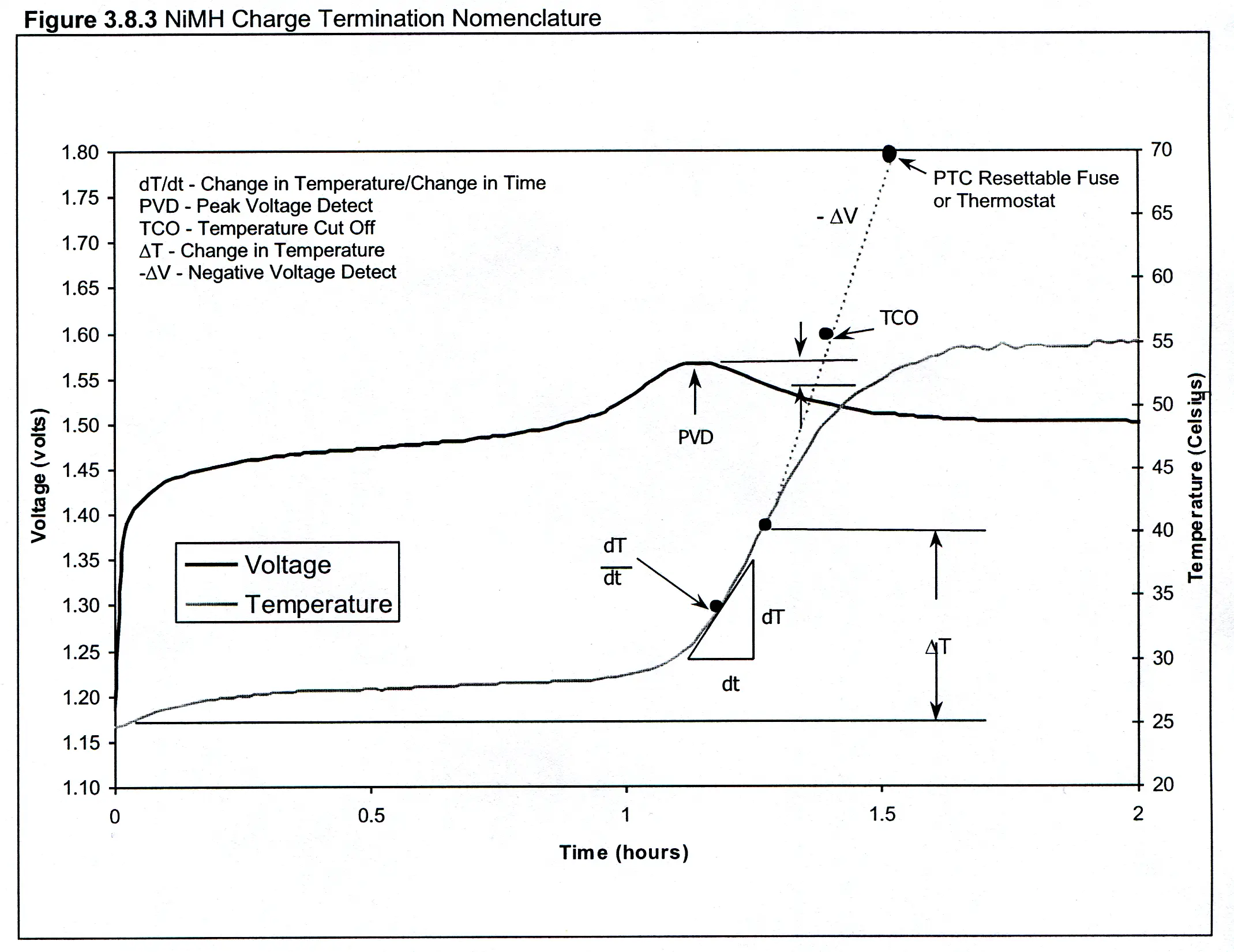
3.8.4 NIMH Temperature and Charge Efficiency
The recommended charging temperature is between 10°C (50°F) and 40°C (104°F). If a NiMH battery is exposed to high temperatures (above 40°C, 104°F) due to overcharging or external heat sources, the charge efficiency (increase in stored cell capacity per unit of charge input) will be decreased. In order to avoid decreased charge efficiency, batteries should have charge control methods applied to limit the amount of overcharge heat that is generated. In addition, it is critical to not place batteries in close proximity to other sources of heat or in compartments with limited cooling or ventilation.
At temperatures below 10°C (50°F) charge efficiency will also decrease resulting in an increase in the amount of time need for charging. Low temperatures inhibit transport capabilities (the ability to move ions within the electrodes) causing the low charge efficiency (see Section 3.7.1, NiMH Capacity and Construction; Rate Capability). Charging below 0°C (32°F) is not advisable
3.8.5 NIMH Charge Methods
Not all charge methods are recommended for all NiMH cell chemistries, seeing they are not designed the same. Different materials are used in various NiMH cells to achieve certain desired performance characteristics. The selection of these materials also affects the charging characteristics of the batteries. Therefore, any method that could cause problems with some batteries has been noted for each charge method. See Figure 3.8.5 Charge Method Specifications for recommended charge currents and charge terminations.
Figure 3.8.5 Charge Method Specifications| Charge Method | Charge Current | Charge Termination | Comments |
|---|---|---|---|
| Slow | 0.02-0.1C | 1. None1 or Timer | Timer rated at 160%C. |
| Standard | 0.1C | 1. Timer | Timer set for 16 hours. |
| Time | 0.1-0.2C | 1. Timer, and 2. TCO = 55°C | Timer rated at 160%C @ 0.1C to 120%C @ 0.2C. |
| Rapid2 | 0.25-0.5C | 1. PVD, or dT/dt, or ΔT, and 2. Timer, and 3. TCO = 55°C | PVD = -ΔV of 3-5 mV/cell dT/dt = ~1°C/1 min rise. Timer rated at 140%C @ 0.2C to 120%C @ 0.5C. |
| Fast2 | 0.5-1.0C | 1. PVD, or dT/dt, or ΔT, and 2. Timer, and 3. TCO = 55°C | PVD = -ΔV of 3-5 mV/cell dT/dt = ~1°C/1 min rise. Timer rated at 125%C. |
| Maintenance | 0.002-0.008C | 1. None | 5-10%C per day at C/128 to C/512 pulse recommended. |
| 1 Not all batteries can be charged without a termination. 2 See Rapid/Fast Charging Procedure (Section 3.8.6) | |||
3.8.5.1 Slow Charge
When charge time is not an issue and maximum rechargeable capacity is desired, the slow charge method is often used. This method uses a charge that is less than 0.1C and for more than 16 hours (see Figure 3.8.5 Charge Method Specifications). Yet, with the recent developments of some NiMH cell chemistries to be better suited to faster charging methods, slow charging is not recommended for all NiMH batteries.
3.8.5.2 Standard Charge
This method can be used for most of the NiMH cell chemistries. The standard charge is a simple system using a charge rate of 0.1C for 16 hours (see Figure 3.8.5 NiMH Charge Methods). Since the charge rate is low and the charge is terminated after 16 hours, there is less risk of overcharge and increased temperatures. The downside to this method is the inability to detect how much charge a battery has at the time charging begins. Thus, a battery that is at a 60% depth of charge (DOD), or 40% state of charge (SOC), which is charged using this method will see the same amount of charge as a fully discharged battery. This leads to the overcharging of the partially discharged battery before the time termination occurs.
3.8.5.3 Time Charge
For the faster timed charge method, batteries can typically be charged in 6 to 16 hours. This method of charging NiMH batteries requires the most attention before selection. Since this method uses higher rates of current (see Figure 3.8.5 Charge Method Specifications), two methods of termination are needed: timed and TCO. The later of the two terminations would require the battery to include a thermistor to detect the temperature during the charge cycle. If only a timed charged termination was used, the battery may be pushed into overcharge, especially if a partially discharged battery was charged using this method. For some NiMH cell chemistries this would significantly deteriorate battery performance.
3.8.5.4 Rapid Charge
The Rapid Charge method is good for applications needing a faster charge time, but the battery compartment does not allow for good heat dissipation. Rapid charge methods typically charge in 2.5 to 6 hours using charge rates of 0.25C to 0.5C (see Figure 3.8.5 Charge Method Specifications). This method of charging uses PVD, - ΔV, dT/dt or ΔT with time backup. For further charging details see Section 3.8.6 Rapid/Fast Charging Procedure. This system usually uses a temperature backup to ensure against overcharging. The advantage of this charge method is the ability to safely charge batteries that are at any state of charge. In other words, a partially discharged battery can be charged without the risk of being overcharged. The disadvantage to this type of system is the added complexity and expense of the charger.
3.8.5.5 Fast Charge
When time is a limited resource and there is good heat dissipation, Fast Charge methods are the best approach. Fast Charge methods will charge batteries in 2.5 hours or less. Like the Rapid Charge method, this method has increased charge rates and requires three separate charge terminations (see Figure 3.8.5 Charge Method Specifications). Some of the higher capacity NiMH batteries will not handle a constant 1.0C charge rate. Presently, a good rule to follow is no constant charging above 1.0C or 3.0Amps. For further charging details see Section 3.8.6 Rapid/Fast Charging Procedure. As with the Rapid Charge, the advantages of the Fast Charge method is the ability to safely charge batteries that are at any state of charge in a short period of time. The disadvantages are, again, the added complexity of the charger and expense.
3.8.5.6 Maintenance Charge
Unlike the previous six methods the Maintenance Charge method is not considered a means of charging a discharged battery to full capacity. Rather, this method is used to counteract the occurrence of battery self-discharge when the battery is not in use. See Section 3.9 Battery Storage.
3.8.6 NIMH Rapid/Fast Charging Procedure
The following procedure outlines the six steps for fast or rapid charging a NiMH battery. These steps will provide insight into what the charger chip manufacturers have tried to incorporate into their chips.
3.8.6.1 Initialization Charge
Before fast or rapid charging a battery, a trickle charge rate is recommended. Starting with a pulsed C/10-C/50 trickle charge is good for two reasons. First, to bring up the temperature if the batteries are cold, and second, to verify there are no problems with the batteries or charging circuitry.
3.8.6.2 Temperature Measurement
Before fast or rapid charging can begin, the temperature must be between 10°C and 40°C. This is done as part of the trickle charge step. If a battery has been exposed to lower temperatures, the battery temperature must be brought up to above 10°C before fast charging can begin. Furthermore, take note that the dT/dt parameters will be reached at the beginning of a fast charge on a cold battery, thus resulting in the premature termination. Many chargers incorporate a "low temperature inhibit" to nullify this event.
3.8.6.3 Pack Voltage Measurement (PVM)
The measurement of the battery pack voltage is also part of the trickle charge step. A pack voltage measurement (PVM) can be used to verify that the battery is at the proper voltage level and to verify there is current available for charging. Time (few seconds to 10 minutes) and voltage (1.1 volts x # of cells) are dependent on the type and number of cells used. If the voltage of the battery is not reached in the set time (usually about 20 minutes) the charge is terminated. For PVM a pulse charge at a rate of C/10 to C/50 is recommended, but a constant charge rate of C/10 to C/50 can be used.
3.8.6.4 Rapid/Fast Charge
Rapid charge or fast charge methods require three modes of termination:
- PVD, or –ΔV, or dT/dt, or ΔT
- Timer
- Temperature Cut Off (TCO).
See Table 3.8.5 Charge Method Specification for charge rate information.
3.8.6.5 Top-Off Charge
Top-off charging is only used if the fast charge or rapid charge does not fully charge the batteries. This occurs with some dT/dt and T terminations. Before using a dT/dt or T fast charging, the charging and termination parameters need to be tested inside the device. Since a constant current top-off charge has a tendency to remove energy, the top-off charge is best to be done as a pulse charge. The top off charge is terminated by time and is C/10 to C/40 of the rapid charge rate.
3.8.6.6 Maintenance
A maintenance charge will retain a full charge on the battery until it is removed from the charger. During the first 24 hours after a battery has been charged, it will lose about 5% of its energy caused by the batterys self-discharge. A standard maintenance charge at a C/128 rate is designed to counter this self-discharge. Some NiMH chemistries are able to handle maintenance charge rates up to a C/64 rate. Continuous charging at low rates is not very efficient, therefore, pulse charging is recommended.
3.9 NiMH Battery Storage Overview
Over time capacity and voltage of NiMH rechargeable batteries will decrease when stored or left unused. This is caused by a chemical reaction that takes place within the cells, commonly referred as self-discharge. The affects of self-discharge will be minimized if unused batteries are properly stored. Proper storage of NiMH batteries requires both temperature control and inventory management.
3.9.1 NiMH Storage Temperature and Battery Cycling
Temperature is the major factor affecting the rate of self-discharge of an unused battery. As storage temperatures increase, the self-discharge rate increases thus causing the maximum storage time of a battery to decrease. It is best to store batteries in a temperature-controlled environment so that the maximum storage time can be accurately determined. Figure 3.9.1 Storage Temperature vs. Storage Time shows the range of storage temperatures that NiMH batteries can be stored and the maximum length of time a battery can be left unused before having to be cycled.
Figure 3.9.1 Storage Temperature vs. Storage Time| Storage Temperature | Maximum Storage Time (Frequency of Cycling) |
|---|---|
| 40°C to 50°C (104°F to 122°F) | Less than 30 days |
| 30°C to 40°C (86°F to 104°F) | 30 to 90 days |
| -20°C to 30°C (-4°F to 86°F) | 180 to 360 days |
The energy storage capability of a battery will be decreased if the battery is allowed to completely self-discharge. The affects of self-discharge can be corrected if the batteries are subjected to cycles of charging and discharging. On the initial charge/discharge cycle, the battery will achieve approximately 95% of rated capacity. Full capacity will be achieved on the second and third cycles.
3.9.2 NiMH State of Charge
The state of charge (SOC) of an unused NiMH battery has no influence on the required storage temperature or the maximum storage time (see Figure 3.9.1 Storage Temperature vs. Storage Time). A fully discharge battery will last in storage as long as a fully charged battery. Therefore, NiMH batteries can be stored at any state of charge.
3.9.3 NiMH Storage Guidelines
The key to properly storing NiMH rechargeable batteries is establishing good inventory management practices. To prolong the cycle life and maintain battery performance adhere to the following five guidelines:
- Practice FIFO (First In First Out) inventory rotation.
- Never store batteries under load.
- Store batteries in a temperature-controlled environment (see Figure 3.9.1 Storage Temperature vs. Storage Time).
- Cycle batteries (see Figure 3.9.1 Storage Temperature vs. Storage Time).
- Store batteries at 65% (±20%) humidity.