Protection Classes, Isolation, EMC, and Earthing in Modern Switch-Mode Power Supplies
Background:
When selecting a mains power supply, engineers are often faced with decisions about "equipment class" and "earthing", concepts which are familiar, but whose impacts may be unclear. GlobTek, and other power supply manufacturers, have sought to improve customer outcomes by offering a variety of configurations tailored to specific system-level needs. However, understanding how these configurations align with established equipment classifications can sometimes be challenging. This article aims to clarify the relative advantages and drawbacks of each configuration and how each configuration may be classified.
Theory of Equipment Protection Classes:
Most mains electrical installations around the world are “earth referenced”, meaning a building's neutral conductor is tied to earth somewhere near the service entry point. As humans reside on the planet earth, we too are earth referenced. Because humans and mains power then share a common electrical reference, it is possible for humans to “enter the loop” if inadvertent contact is made with the mains supply. Thus, isolating humans from mains power is essential for safe interaction with mains powered equipment.
An isolated power supply creates a galvanic barrier between the mains supply and its output, effectively “breaking the loop.” This allows for relatively carefree interaction with the output, provided that the output voltage and leakage currents are sufficiently low.
To ensure adequate protection from electric shock, safety standards allow mains powered equipment to follow one of two approaches, corresponding to the protection classes known as Class I and Class II. Both classes are accepted as equivalent in terms of prevention of electric shock, but each take a different approach.
Class I:
In a Class I design, components and materials comprising an isolation barrier meet the requirements for basic insulation, but are not deemed robust enough to reliably prevent shock on their own. A second means of protection is typically realized by a protective earth connection made to the secondary side circuit, usually connected to the output negative.
If there is a failure of basic insulation failure in a Class I design, primary and secondary become inadvertently connected. As a result, a large fault current flows through the protective earth conductor, causing the equipment’s fuse or the building’s circuit breaker to open, which neutralizes the faulty equipment. Because neutralization of the equipment requires that the protective earthing conductor carry a fault current for enough time to cause the protection device to trip, it is important that the protective earth conductor is sized adequately.
For this reason, safety standards stipulate that a protective earth connection is of sufficiently low impedance (<100mΩ, per IEC60601-1) and is tested at a high enough current and for an appropriate amount of time (25A @ 10s, per IEC60601-1, and/or 200% of protection device rating @ 120s, per IEC62368-1).
Equipment using a metal enclosure is often designed as Class I due to large amounts of user-accessible metal, and due to practical difficulties in achieving high levels of isolation between internal wiring and the enclosure. However, it is not rule that metal enclosed equipment must be Class I.
Class II:
In a Class II power supply design, components comprising the primary-to-secondary isolation barrier meet the requirements for reinforced or double insulation. This means that the insulation is deemed of sufficient robustness that a “backup” protective earth connection is not required. Both means of protection are provided by the insulation itself. Double insulation is perhaps the simplest to understand - A second layer of supplementary insulation is added to basic insulation, to form two means of protection. The rationale is essentially that, if one layer of insulation fails, electric shock is still avoided by the presence of the remaining intact layer. In double insulated equipment, the two layers of insulation can be separated and tested individually.
However, in modern switch-mode power supplies, since the introduction of triple insulated wire (TIW), reinforced insulation is almost always used instead of double insulation. Conceptually, reinforced insulation not much different than double insulation, but the individual comprising layers cannot be readily separated, and so the insulation is tested as a whole, and to slightly different standards. Triple insulated wire is a type of wire with three extruded layers of insulation, which combined meet the requirements for reinforced insulation.
“Functional earthing”:
In the present day, power supplies are predominantly designed and built as Class II because the trade-offs involved in achieving Class II construction are minimal. However, it is often advantageous to introduce a connection to earth for “functional” purposes, namely to improve EMI or reduce output leakage current without increasing overall size or cost.
The question that often arises is: “To which class does a functionally earthed power supply belong?”
Unfortunately, the answer is not always straightforward, and the determination is often muddied by inconsistent terminology across safety standards and by varying interpretations between test labs. Proper classification is dependent on the actual design of the power supply in question. The safety report of a given power supply will indicate its classification. Generally, a power supply can only be classified as “Class II with functional earth” if the internal earth conductor is isolated from mains by two means of protection. (i.e. It must meet insulation and creepage/clearance requirements.) The rationale is that, if earth is separated from mains by basic insulation only, then it must be designed as a protective earth, even if the earth connection was introduced to meet a functional need.
For medical equipment, if a protective earth connection is passed to the end system through the power supply’s output connector, then the power supply’s output is typically seen as a protective earth terminal for the medical equipment (ME). As such, most safety labs want to see such a power supply marked as Class I, regardless of whether the internal earth wiring has two means of separation from mains.
Similarly, according to the ICT/ITE standard, markings indicating Class II construction are not allowed on equipment which provides a protective earth connection to other equipment. So, when a power supply has a protective earth connection made to its output, it must be regarded as Class I, even if its internal construction is otherwise Class II in nature. This is in alignment with the medical standard, as mentioned above.
If earth is connected to a point other than the output, determination of class again varies depending on the actual level of isolation between earth and mains, internal to the power supply.
For medical systems, the level of isolation between earth and power supply output may also be relevant in implementing BF and CF applied parts. It is therefore important to check the safety report of the power supply in question to confirm that the isolation scheme employed is compatible with the end-use application.
GlobTek Input Configurations:
The term “input configuration” refers to the number of conductors connected to the AC input of the power supply, and if an earth connection is present, the point to which earth is connected. Configurations can be either “floating” or “earthed”. Floating means that the output is not tied directly to earth potential, and floats at some common-mode voltage with respect to earth. In an earthed configuration the output is tied to earth and so no common-mode voltage can develop between the output and earth.
For floating configurations, it is typical to measure around one-half the AC line voltage between output and earth, which at first glance, can seem alarming. This common-mode voltage is a result of stray capacitance between the output and earth. The effective source impedance is very high, and so this voltage collapses when loaded with even a modest resistance. i.e. It's ability to source current is inherently limited to safe values. (See: "AC Leakage Current" below.)
Between the two basic types, floating and earthed, neither is categorically better than the other, and the reasons to select one over the other depend on the application.
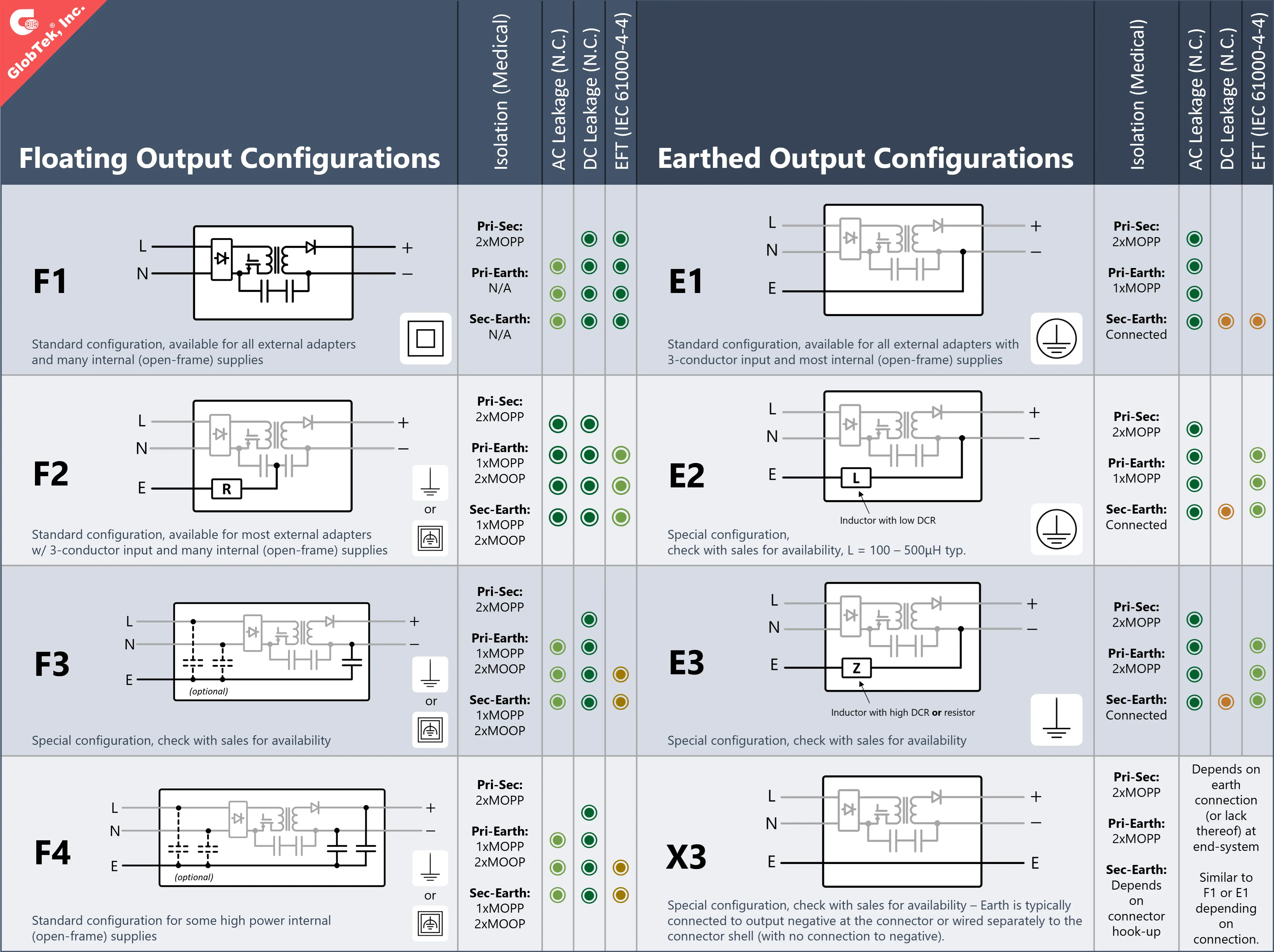
GlobTek provides a range of input configurations to suit different system requirements; configurations starting with “E” tie the output to earth, while those labeled with “F” are floating. Configurations which do not fit neatly into either box are denoted with an “X” prefix. The simplest configurations are types E1 and F1, correlating to the most basic definitions of Class I and Class II.
E1: Three-conductor input, protective earthed tied to output negative (Class I)
F1: Two-conductor input, floating output (Class II)
The E1 configuration is the default earthed configuration, and works for many customers. However, the direct pass-through of the earth wire to the customer system can sometimes cause conducted EMI and EFT immunity issues. The F1 configuration is commonly used in compact power adapters and can operate in installations without an earth connection. In general, F1 performs well, but as power ratings increase, functionally earthed configurations become increasingly attractive by comparison, typically offering size and/or cost advantages. e.g. A functionally earthed power supply can reduce filter size by a sizable fraction compared to the same class of power supply with F1 construction.
Depending on the system’s EMC requirements or the design of the power supply, the below alternative input configurations may offer certain benefits, either for the power supply, the end-application, or both. Please note that certain input configurations may not be available for the GlobTek model under consideration. Contact GlobTek sales for details.
E2: Three-conductor input, protective earthed tied to output negative through an inductance (Class I)
E3: Three-conductor input, functional earth tied to output negative through a high DCR inductance or resistance (Class II with FE, ICT/ITE only)
F2: Three-conductor input with functional earth to center of bridging Y-caps, floating output (Class I or Class II with FE; see particular safety report for classification)
F3/F4: Three-conductior input, Y-cap(s) between output and earth (Class I or Class II with FE; see particular safety report for classification)
X3: Three-conductor input, direct pass-through of protective earth to customer system, but no connection of earth to power supply (Class I)
The below table summarizes the range of input configurations available from GlobTek. The relative performance levels assigned to each assume the underlying design (model) is the same. There indeed appear to be configurations with better overall performance than others. A reasonable question that arises is: “Why not always pick the configuration with the highest overall performance?" As alluded to above, some designs are incompatible with, or less suited to use with particular input configurations, due to mechanical, electrical or EMC constraints. GlobTek’s standard configurations are chosen to balance ease of implementation with power supply cost and size competitiveness. However, since each end-system implementation is different, trying an alternative configuration may prove useful in addressing certain system-level issues.
Medical Isolation and Applied Parts
Per IEC60601-1, if the output of a power supply is separated from mains by 2xMOPP, it is considered a secondary circuit. Patient connections must be isolated from mains by 2xMOPP, which is guaranteed by use of a 2xMOPP medical power supply. It should be noted, however, that a secondary circuit must not be connected through to the patient connection of a Type-BF or Type-CF applied part. The medical system must isolate patient connections from secondary circuits by an additional 2xMOPP, though the insulation requirements for this second barrier are typically lower based on lower working voltages. Consideration must also be given to which parts are operator accessible and which are patient accessible.
AC Leakage Current:
By definition, patient leakage current can only be measured if there is an applied part (and associated patient connection), and a power supply inherently does not contain any patient connections. Still, as the power supply often has a large influence on system-level leakage current, medical power supplies are typically designed as if the DC output was a patient connection. In the specification of a medical power supply, this leakage current is often referred to as "output touch current" or "output leakage current". This is the leakage current that arises due to capacitances bridging the primary-to-secondary isolation barrier. In most medical switch-mode power supplies, two Y-class capacitors are installed between primary and secondary commons to shunt high frequency switching noise away from large external loops. This capacitance, and its 50/60Hz impedance, accounts for roughly 90% of the output leakage current in a typical power supply. Some leakage current can arise as a result of high frequency switching, but mains frequency leakage generally dominates by a significant margin.
IEC60601-1 models the human body as a 1KΩ resistance. The leakage current is taken as the voltage generated across this resistance, where 1mV = 1µA. The IEC60601-1 test applies the measured voltage to a 1KHz low-pass filter, which accounts for the human body’s decreasing sensitivity to electric currents at higher frequencies. Leakage current testing aims to simulate the current “felt by” a human standing on earth, so for the test, one leg of the 1KΩ resistor is tied to test earth, and the other leg (or "arm") is tied to the power supply's output, or other user-accessible parts. This setup is used for both AC and DC leakage measurements.
It's important to note the distinction between "output touch current" and "earth leakage current", as these are sometimes confused. If there is an earth connection made to the unit for a functional or protective purpose, the power supply may drive a small amount of current through the green/yellow earth wire in the AC input cord as a collateral effect. In most contexts, this current is not considered dangerous, as the ways in which humans can interact with this current are limited. Yet, to avoid tripping RCD/GFCI systems and to minimize differences in earth potential between neighboring equipment, this current needs to be kept reasonably low.
DC Leakage Current:
In earthed output configurations, DC leakage currents become a possibility because the output is directly referenced to earth. Recall from the previous section that the leakage current measurement concerns the current through an earth referenced human. When the power supply's output is earthed (e.g. E1 configuration), then there is a shared reference between the 1KΩ measurement resistor and the DC output. (For floating configurations, the output is only AC coupled to earth, so DC leakage is not possible.)
Assuming output negative is tied to earth, output positive could pose a DC leakage concern if user accessible, as an output voltage of just 0.1VDC drives a current of 100µADC through 1KΩ (the IEC60601-1 limit). However, connectors and systems are typically constructed such that positive conductors are not accessible, so this is usually not an issue.
Still, a DC leakage issue due to the negative conductor can still arise if the following conditions are met:
- The system is powered by an external adapter with a two-conductor output cord
- The earth conductor is tied to DC negative inside the adapter
- The end equipment bonds its metal enclosure and/or exposed metal parts to DC negative/earth
- The resistance of the adapter’s negative output conductor (in the cord) is relatively high
With particular emphasis on item four, if a voltage drop is developed across the negative conductor, due to Iout × Rcord, the system’s enclosure will become “lifted” by Iout × Rcord with respect to earth. When this voltage is greater than 0.1V, then touching the system enclosure will generate a DC leakage current exceeding 100µADC. As an example, a 14AWG conductor has a resistance of ~8.5mΩ/m. For a 1m cable length, not including the resistance of the connector, a maximum of 11.8A can be drawn through this conductor without exceeding the 100µA limit, assuming the system enclosure is tied to DC negative.
For sufficiently heavy gauge output cords and/or low enough operating currents, this is a non-issue, and a simple two-conductor output cord may be used. Otherwise, the output cord can be exchanged for a 3-conductor cord with a separate earth conductor that does not carry current during normal operation. Note that, as always, the earth conductor should be sized for protective earthing if it is used as such.
Electrical Fast Transients (EFT), IEC61000-4-4 Immunity:
The electrical fast transient (EFT) immunity test simulates the effects of switching reactive loads with mechanical switches, relays, or contactors. Separating contacts creates an arc which collapses and reignites in rapid succession, creating a burst of pulses with very fast rise times. In the standardized IEC61000-4-4 test, the burst contains 75 pulses, each with a 5ns rise time and 50ns fall time. Pulses are repeated every 10µs (100KHz pulse repetition rate), and bursts are repeated every 300ms. The total test time is one minute (minimum) per condition. The disturbance is injected through a standardized coupling network onto AC line, AC neutral, and earth connections, individually, and in all possible combinations of the three. Note that the earth connection is among the tested ports, as it is not assumed that the equipment’s earthed parts will be held at “true” earth potential otherwise. That is, a disturbance originating from the earth connection can be a real possibility, depending on the relationship of the earth connection to EFT sensitive circuitry.
In the EFT test, the equipment under test is laid on a metal reference ground plane (RGP), separated by some distance. The pulse voltages are applied between the tested conductor(s) and the RGP, which means that EFT issues are primarily common-mode in nature. EFT pulses travel through the equipment, and return to the generator via the RGP. Stray capacitance between the equipment and RGP serves as the main coupling mechanism between the two.
EFT can prove particularly challenging due to its broad frequency content, with significant energy content between 100KHz – 100MHz. In digital circuitry, alignment (in time) of an EFT rising/falling edge and a digital transition can lead to corruption of data, loss of a communication link, and so on. A pointed, localized solution can be applied to the sensitive circuitry with minimal size or cost impact. Otherwise, bulk suppression by way of common-mode choke or ferrite is one of a few typically prescribed solutions. Impedances on the order of a few 100 ohms to 10’s of kiloohms may be required for sufficient attenuation. Peak EFT currents, as measured from the generator’s output, are typically on the order of 10A, so suppression components should be sized to avoid magnetic saturation or electrical overstress, if applicable.
All GlobTek power supplies are designed to be immune to EFT transients, regardless of selected input configuration. However, the selected input configuration can affect the end-system’s exposure to the transient, and system-level immunity varies. For example, GlobTek’s E1 configuration, which is widely used, directly couples an EFT pulse into the end-system via the earth wire. In many cases, the system will be undisturbed. But, if a failure occurs, the customer should consider whether a floating configuration would be suitable as an alternative, and if not, inquire about the availability of the E2 configuration for the particular model in question.
Electrostatic Discharge (ESD), IEC61000-4-2 Immunity
Although not mentioned in the above table, input configuration has some bearing on system-level ESD testing, or at least, the test protocol used. For earthed configurations, after ESD is applied to the DC output, any residual charge remaining on the secondary-side is bled off by the earth connection. For floating configurations (absent a direct earth connection to the output), there is no "DC bleed-off path". So, each successive ESD strike causes charge (and voltage) to ratchet up until the dielectric strength of a component is exceeded, leading to a violent release of accumulated charge. The intensity of this breakdown is often sufficient to damage components in the discharge path.
Therefore, for floating configurations, it is imperative to follow the method prescribed by IEC61000-4-2 section 7.2.4 for "ungrounded equipment". See below:
"Ungrounded equipment, or ungrounded part(s) of equipment, cannot discharge itself similarly to class I mains-supplied equipment. If the charge is not removed before the next ESD pulse is applied, it is possible that the EUT or part(s) of the EUT be stressed up to twice the intended test voltage...To simulate a single ESD event (either by air or by contact discharge), the charge on the EUT shall be removed prior to each applied ESD pulse."
Note that the presence of an earth connection (whether functional or protective), usually has little influence on the ability for the power supply or the end-system to pass ESD testing. The frequency content of an ESD pulse is similar to that of EFT. The inductance of a few meters of earth wire in input cabling or building wiring is high enough to mostly decouple the EUT from AC mains at ESD frequencies. ESD return currents arise from stray capacitances between the EUT and test plane. To that point, products employing shields or metal plates which establish "good" capacitive coupling (perhaps a 100pF or more) to the test plane have the potential to divert ESD currents away from sensitive circuitry, given the ESD can be redirected to the plane somehow. Whether this shield or plate is connected to earth is mostly irrelevant, for the reasons noted above.
Output Connector Hook-Ups
External power adapters, with a connector attached to the output cable, are configurable in a number of ways. By default, if not noted on the specification, GlobTek power adapters are configured according to connector hook-up "0". All output configurations noted above may be combined with hook-ups "0", "A", or "B". Hook-ups "C" and "D" may be combined with "E1", "E2", "E3", and "X3" configurations, but should not be combined with "F2", "F3", or "F4" because the proximity of the earth connection, in relation to the output pins/conductors, typically invalidates secondary-to-earth creepage/clearance requirements.
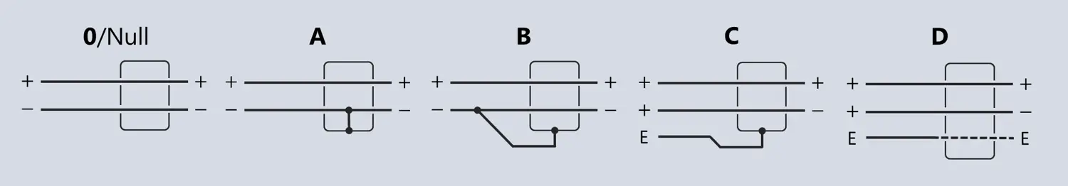
Text descriptions of GlobTek output connector hook-ups are given below:
0/Null: Connector with plastic or metallic shell, no connection of output to shell
A: Connector with metallic shell, typ. used with 2-conductor / 1C + shield output cable, DC- connected to shell
B: Connector with metallic shell, typ. used with 3-conductor / 2C + shield output cable, 3rd conductor connected to DC- at power adapter & connected to connector shell
C: Connector with metallic shell, typ. used with 3-conductor / 2C + shield output cable, earth connected to 3rd conductor & connector shell, earth isolated from output
D: Connector with metallic shell, typ. used with 3-conductor / 2C + shield output cable, cable shield cut short of connector (no connection) or connected through to connector pin, earth isolated from output
Earthed output configurations experiencing DC leakage issues as detailed earlier can specify hook-ups "B", "C" or "D" to resolve the issue. Ensure that the additional conductor is sized as a protective earth conductor.
In hook-ups "C" and "D", earth is isolated from the DC output. The degree of isolation depends on the insulation of the raw cable material and the spacing between the earthed shell/pins and the DC output pins. Many times, there is insufficient creepage/clearance between adjacent pins (or between pins and shell) to pass medical hi-pot test requirements. In cases where such levels of isolation are required, be sure to specify an appropriate output connector, and that the raw cable meets requirements for solid insulation according to safety standard in question.
Conclusion
Modern switch-mode power supplies must balance safety, EMC performance, and regulatory compliance through thoughtful design of isolation and earthing schemes. GlobTek offers a range of input and output configurations to optimize performance for different applications. Understanding the relationships between isolation, earthing, and EMC behavior is key to achieving reliable, safe, and standards-compliant system performance.
October 2025